 –>
–>


Aberlink 3D
3D Measurement Software
Version 4.23.5.26 of our Aberlink 3D measurement software has been released Click here to download the latest software packages
×
- Info Request
- Catalogue

Making Measurement Easy
The whole philosophy for Aberlink is to make measurement easy. Aberlink 3D software has been written by engineers for engineers and sets the industry standard for ease of use.
Designed around a graphical interface, Aberlink 3D can work in 2D or 3D, on manual or CNC CMMs and is equally at home when used with either touch, scanning or vision systems.
It is easy to understand why Aberlink 3D has become the software of choice not only for Aberlink, but for numerous other manufacturers of measuring devices around the world.
Revolutionary
Aberlink 3D software is revolutionary. For example, Feature Predict enables you to just take measurement points and the software automatically determines if you are measuring a Plane, Line or Circle feature.
Move from feature to feature and the software predicts what you are measuring. As a component is measured a representation of it is built up on the screen. The user simply clicks on the measured features to call up dimensions exactly as they would appear on a drawing.

Affordable
Aberlink is the only leading CMM manufacturer to offer zero-cost annual software maintenance contracts or subscriptions and free software updates, including all major releases.
2. Polyworks Inspector :3D Measurement Software

Discover the Power of PolyWorks on Aberlink CMMs
Unleash the full potential of your Aberlink CMM with PolyWorks! Industry-leading inspection software that delivers precision, performance, and productivity without the premium price tag. From advanced GD&T tools to offline simulation and automated path planning, PolyWorks transforms your inspection process. Now with full support for Kreon Zephyr laser scanning alongside traditional touch and contact probing, it’s a future-proof solution for every measurement challenge.
PolyWorks + Aberlink: Big Capability. Small Cost.
High-productivity CNC CMM Solution
PolyWorks Inspector has reinvented the way inspection projects are set up and executed on CNC CMMs, within a flexible, user-friendly, and efficient CNC CMM operational paradigm.
- Reduce the complexity of your CMM programming tasks
Shorter and easy-to-understand CNC CMM sequences, as our nominal features, dimensions, and reports are created and managed outside of the sequence editor. - Accelerate the sequencing process while staying in control
Select objects to be measured and let the sequence editor automatically find the proper tool orientations, the optimal measurement order, and collision-free measurement paths. - Fix sequencing mistakes intuitively
Intelligent sequence editor provides immediate feedback when illogical or incorrect operations are detected, and lets you repair detected mistakes in a single click. - Avoid potential collisions automatically
Powerful collision analysis and avoidance technologies that detect potential tool collisions in real time* and automatically modify the toolpaths to prevent them. Offline simulation also available for risk-free program validation.*Real time collision detection is only currently available on Renishaw controllers. Available on Deva controllers in early 2026


Review inspection results efficiently
- Control views
Organise projects containing hundreds of dimensional and GD&T controls into small and logical groups of controls, with individual controls tied to specific alignments and coordinate systems. - First Article Inspection Reports
Quickly publish an AS9102 and PPAP-compliant First Article Inspection Report by measuring a piece from the first production run and transferring the results automatically to Excel using PolyWorks|ReportLoop™. - Statistical Process Control (SPC)
Assess the repeatability and predictability of your manufacturing processes with multipiece statistics automatically calculated for object dimensions and surface deviations. - Measurement System Analysis
Design and carry out repeatability and Gauge R&R studies and publish results in elegant, content-rich Excel templates using PolyWorks|ReportLoop™.
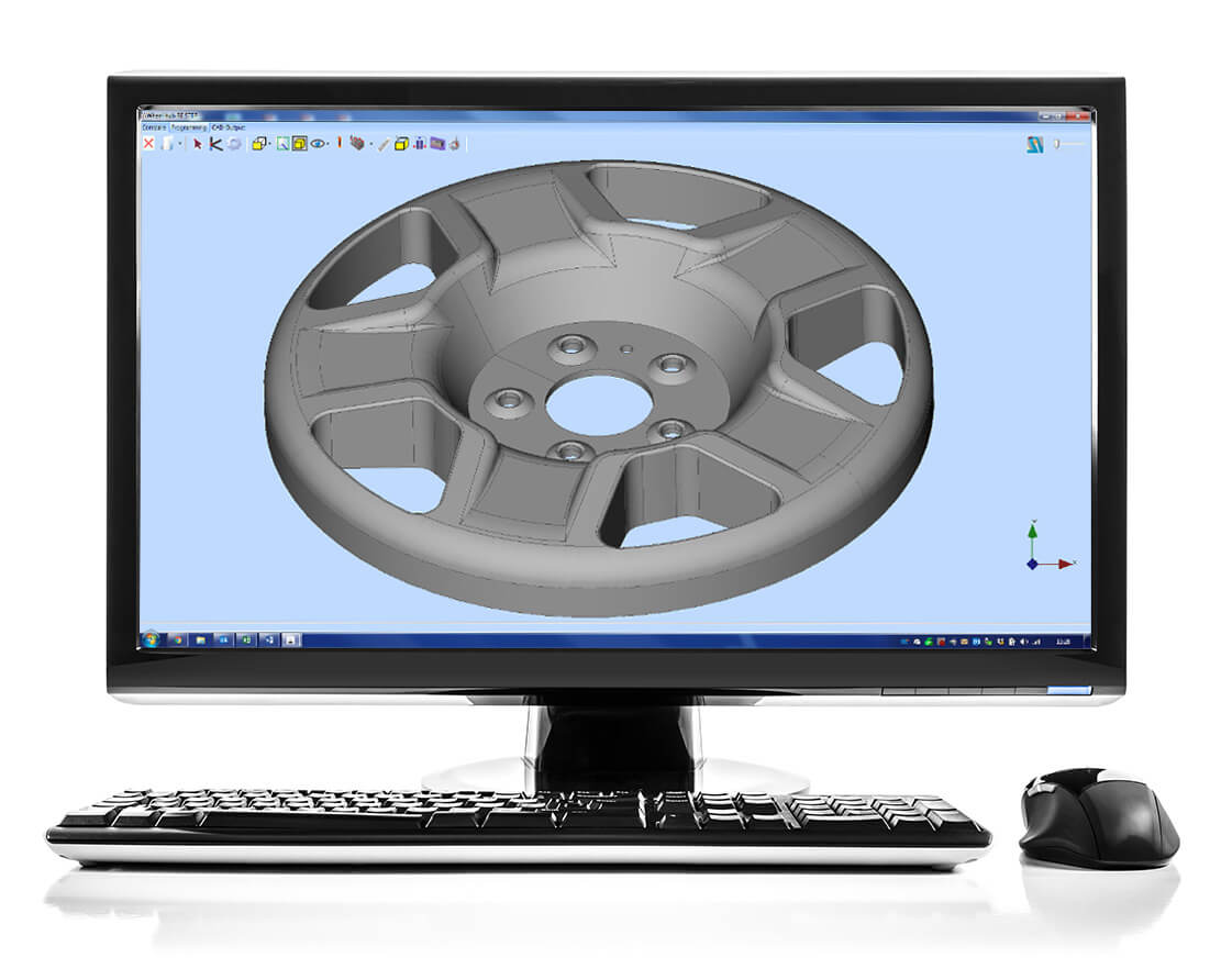
3. CAD Comparison : Aberlink 3D Module

Compare Points to a CAD Model
The Aberlink CAD Comparison software module enhances Aberlink 3D with the capability to compare measured points to a CAD model. This may be the best way to measure complex geometries, or to inspect parts for which drawings do not exist.
Complex, Simplified
Powerful alignment routines allow measurement points to be best-fitted to the model. Colour coded errors can then be displayed on the model to produce both graphical and tabulated reports that are extremely clear and very easy to understand.
Aberlink’s CAD comparison module allows the input of either STEP or IGES files as standard and allows reports to be exported as an Excel spreadsheet. It really does make measuring complex parts easy, whether on a manual or CNC CMM.

Key Features
CAD Formats
- IGES and STEP import and export
- DXF export
- Re-scale Models
- Simple measurement of complex parts
Alignments
- Point cloud best-fit
- Feature best-fit
- Best-fit constraints
Report Formats
- On CAD fly-out labels
- Colour deviation whiskers
- Colour point markers
- Configurable colour options
- Combine multiple views
- Graphical and tabulated reports
- Export to Excel
4.

Generate Programmes Offline
For many years Aberlink 3D software has been setting the industry standard for both ease of use and speed of programming. However, until now this has been best done by using the teach-and-repeat method of programming when measuring a component. But what if you want to prepare the measurement programme before you even have the first component?
Familiar, Easy Programming
Introducing our programming from CAD software module, which in true Aberlink fashion, allows the simplest programming possible from either an IGES or STEP CAD model, either on the CMM or offline as a virtual CMM.
If you can use Aberlink 3D software then you will already know how to use the CAD programming module – it couldn’t be easier. Rather than taking measurement points on a component, you can now just click on the surface of the model where you would like the points to be taken.
Feature Predict works in the same way as when measuring, for instance, if you click in four places on the same plane on the model, then the software will automatically create a Plane Measure unit with those four points in it. Then click on a different feature and it will automatically close the Plane window and look for another feature. If you click on a circular feature it will take just one click to produce a circle or two for a cylinder. Suddenly programming in Aberlink 3D just got even easier!
6. Vision Software : Aberlink 3D Module

Enhance Your Aberlink CMM with Vision technology
The Aberlink Vision Software module enhances the capability of Aberlink 3D with a set of powerful vision measurement tools.
Originally written to work exclusively with Aberlink’s revolutionary CMM Camera system, allowing the use of touch probe and non-contact on the same machine, the advanced vision software module is now used extensively by many other vision machine manufacturers.

Optical Accuracy
Measure geometric and complex shapes easily, features, scan profiles and inspect threads using high-accuracy edge detection and high-speed optical scanning. Simulate crosshairs and overlays, and control the camera and light settings, all from within the software.
Featuring, fully automatic edge detection tools which can be used in both manual and CNC mode ensuring fast and repeatable results without relying on the skill of the operator.
Dimensions can either be called up by clicking on the measured features in the normal way, or alternatively measurement points can be best-fitted against a DXF file. As well as edge detection the operator may use either full cross hairs or mouse cross hairs with other advanced tools available including « smart measure », centre line detection, an « all edge points » function, a « thread measure » tool and a « screen ruler » for quick measurements between any two points on the image.